Description
1. 9V-40V DC power supply
2. H-bridge bipolar constant phase current driver
3. Up to 4.0A eight output current selectable
4. 6 sub-division modes up to 32 sub-divisions selectable
5. Input signal high-speed optical isolation
6. Standard common positive single pulse interface
7. Offline hold function
8. Semi-enclosed enclosure for more demanding environments
9. Provide energy-saving semi-automatic current lockout function
10. Built-in temperature protection and over-current protection
11. Applicable stepping motor: 42, 57, 86 type 2-phase 4-phase (4 wire 6 wire 8 wire)
12. Weight: about 201g
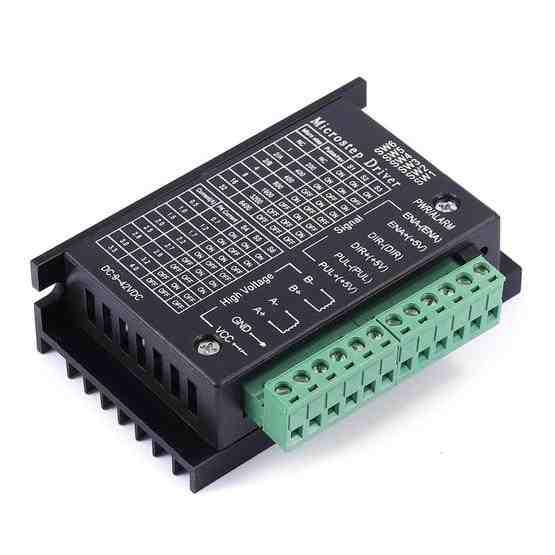
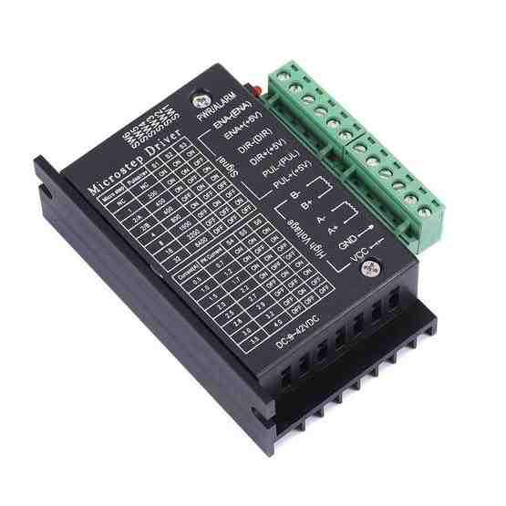
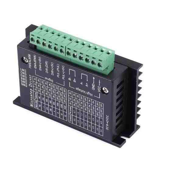
Wiring terminal definition description:
-Signal input terminal:
1. CP+: pulse signal input positive terminal
2. CP-: pulse signal input negative terminal
3. DIR+: motor forward and reverse control positive terminal
4. DIR-: motor forward and reverse control negative terminal
5. EN+: motor offline control positive terminal
6. EN-: motor offline control negative terminal
-Motor winding connection:
1. A+: connect motor winding A+ phase
2. A-: connect to motor winding phase A-
3. B+: connect motor winding B+ phase
4. B-: connect motor winding B- phase
-Connections for operating voltage:
1. VCC: DC power supply positive ( note: 10V <VCC <42V)
2. GND: DC power supply negative
-Input signal interface has two connection methods: users can use the common anode connection method or common cathode connection method according to the need
1. Common anode connection: connect CP+, DIR+ and EN+ to the power supply of the control system, if the power supply is +5V, then it can be connected directly, if the power supply is greater than +5V, then it is necessary to add another external current limiting resistor R, to ensure that the internal optical coupler of the driver can provide a driving current of 8-15mA. pulse input signal through the CP-access; at this time, DIR-, EN- in the low level of active
2. Common cathode connection: connect CP-, DIR- and EN- to the ground of the control system (SGND, isolated from the power supply ground); the +5V pulse input signal is added through CP+; at this time, DIR+ and EN+ are active at high level. the value of current limiting resistor R is the same as that of common anode connection
3. Note: the EN terminal may not be connected, the motor rotor is in a free state (offline state) when EN is valid, then you can manually rotate the motor rotor to do the adjustment that suits you. after the manual adjustment is completed, set EN to invalid state to continue the automatic control

