Discover and buy more than 230,000 products

Open4337-C Standard, LPC Development Board
Item ZY14412144

Warehouse: CN
Lead time: Item will be ready for ship between 29 Jul and 31 Jul 2025

Description
Overview
Open4337-C is an LPC development board designed for the LPC4337JBD144 microcontroller, consists of the mother board and the MCU core board Core4337.
The Open4337-C supports further expansion with various optional accessory boards for specific application. The modular and open design makes it the ideal for starting application development with NXP LPC series microcontrollers.
What is on the mother board
1. MCU core board connector: For easily connecting the MCU core board
2. ZigBee connector: For connecting ZigBee module
3. ONE-WIRE interface: Easily connects to ONE-WIRE devices (TO-92 package), such as temperature sensor (DS18B20), electronic registration number (DS2401), etc.
4. I2C0 | I2C1 interface: Easily connects to I2C peripherals such as I/O expander (PCF8574), EEPROM (AT24Cxx), etc.
5. I2S0 interface: For connecting I2S modules such as Audio module, etc.
6. PS/2 interface: Easily connects to PS/2 keyboard and/or mouse
7. UART1 interface: Easily connects to RS232, USB TO 232, etc.
8. UART2 interface: Easily connects to RS232, USB TO 232, etc.
9. 8 Bit EMC interface: For connecting NandFlash module, etc.
10. SSP1 interface: Easily connects to SPI peripherals such as DataFlash (AT45DBxx), SD card, MP3 module, etc.
11. SDIO interface: For connecting Micro SD module, features much faster access speed rather than SPI
12. ADC+DAC interface: For ADC/DAC testing
13. CAN1 interface: For connecting CAN module
14. CAN0 interface: For connecting CAN module
15. LCD interface: For connecting touch screen LCD
16. ETH interface: For connecting ETH module
17. USB interface: Converts to UART through an onboard USB to UART convertor PL2303
18. 5V DC jack
19. 5V/3.3 V power input/output: Usually used as power output, also common-grounding with other user board
20. MCU pins connector: All the I/O ports are accessible on expansion connectors for further expansion
21. ZigBee programming/debugging interface: For debugging ZigBee module
22. PL2303, onboard USB to UART convertor
23. Power indicator
24. PL2303 TX-LED / RX-LED, UART transmitting/receiving indicator
25. LEDs: Convenient for indicating I/O status and/or program running state
26. User key: Convenient for I/O input and/or interact with running code
27. Joystick: Five positions
28. Power supply switch, 5V DC or USB
29. ZigBee reset button
30. PL2303 jumper: Supports programming and/or UART debugging
31. SD card detect jumper: Enable SD card detection function
32. PS/2 jumper
33. LEDs jumper
34. User key jumper
35. Joystick jumper
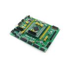
What is on the Core4337
1. LPC4337JBD144: The LPC ARM Cortex-M4/M0 dual-core microcontroller:
- Core: Cortex-M4 processor, 204MHz Max
- Core: Cortex-M0 coprocessor, 204MHz Max
- Package: LQFP144
- I/Os: 83
- Memories: FLASH total 1M, SRAM total 136kB, ROM 64kB, E2PROM 16kB, OTP memory 64 bit
- Interfaces:
-- 1 x SPIFI, 1 x 10/100T MAC
-- 1 x High-speed USB2.0 Host/Device/OTG
-- 1 x High-speed USB 2.0 Host/Device
-- 1 x 550 UART, 3 x 550 USART, 1 x IrDA
-- 2 x CAN 2.0, 2 x SSP, 1 x SPI, 1 x Fast-mode Plus I2C
-- 1 x standard I2C-bus, 2 x I2S, 1 x EMC, 1 x SD/MMC
-- 1 x PWM, 1 x QEI, 1 x 10-bit DAC, 2 x 10-bit ADC
2. AMS1117-3.3 (on bottom side), 3.3V voltage regulator
3. LM3625-H (on bottom side), USB power management device
4. QSPI FLASH solder pads (on bottom side), for soldering external Flash if required
5. Power indicator
6. USB1 VBUS LED
7. USB0 VBUS LED
8. Reset button
9. 12M crystal oscillator
10. 32.768K crystal, for internal RTC with calibration
11. JTAG/SWD interface: for debugging/programming
12. USB1 interface:
- Device mode: communicating with computer
- Host mode: communicating with USB devices (such as USB Flash Drive) through an adapter cable
13. USB0 interface, features USB OTG function
14. MCU pins expander, VCC, GND and all the I/O ports are accessible on expansion connectors for further expansion
15. 5Vin power input, power the core board from external supply (while working on USB HOST/OTG mode, a 5V power input is required)
16. BOOT configuration
17. VBAT selection jumper
- Short the jumper to use system power supply
- Open the jumper to connect the VBAT to external power supply, such as battery
18. USB PWR OUT jumper
- Short the jumper: powered from USB1 VBUS (it's possible to provide power to the mother board via the 5V pin)
- Open the jumper: powered from the mother board
19. USB1 jumper
- Short the jumper when using USB1
- Open the jumper to disconnect from I/O port
20. USB0 jumper
- Short the jumper when using USB1
- Open the jumper to disconnect from I/O port
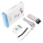
Package Contents
1. Open4337-C development board x 1
2. USB type A plug to mini-B plug cable x 1
3. 4-pin wire x 2
4. 2-pin wire x 2
5. USB power cable x 1
6. Software CD x 1
Related products